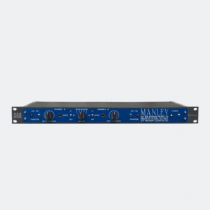
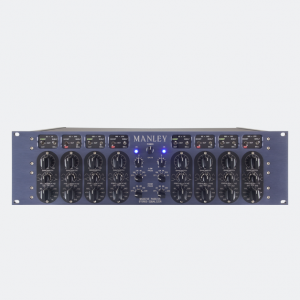
Description
Proudly from our beginning, we at MANLEY LABS have been closely involved with numerous mastering facilities around the world. For these most demanding engineers in our industry, we have created specialized products such as our all-tube tape repro head amps, digital converters, high-powered vacuum tube monitor amplifiers, through to custom monitoring consoles, all the way up to complete facility design and installation.
THE MASTERING VERSION
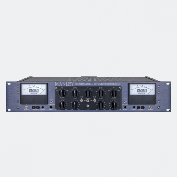
The Mastering Version of our Variable Mu® Limiter Compressor incorporating detented and logable steps built with 1% metal film resistors on sealed gold-contact Grayhill switches is available. NO, we will not mod a “normal” unit to the Mastering Version. The Mastering Version of the Variable Mu Limiter Compressor uses expensive Greyhill rotary switches with gold contacts where conductive plastic pots were used. The steps are determined with a large number of 1% precision metal film 1/2 watt resistors. The best conductive plastic pots only have 10% or 20% tolerance. The ten fold improvement in precision helps a great deal in left-right matching. There is a subtle audible improvement with stepped switches as well. Audiophile HI-FI often uses that technique to wring the last drop of performance out of a preamplifier. And I bet you wanted stepped switches mostly for resets.
The INPUT LEVEL is a five position switch with a generic optimum setting of “0” in the 12:00 position. Each step in either direction is 2 dB. For reference, Unity Gain is “0”.
The OUTPUT Attenuators are in half dB steps. Reference Unity is -11.5 or fully counter-clockwise. You might think of these as “gain makeup”. They are marked technically, in that “0” or fully clockwise has zero attenuation in the circuit. The tube circuit actually has 15.5 dB of gain. The Input attenuator at “0” removes 4 dB and the Output attenuator removes the last 11.5 producing “unity”. With a little compression the “gain make-up” available with the Output Attenuator is very handy.
The Threshold is in half dB steps calibrated to LIMIT mode. In Compress the steps are approximately 1/4 dB. There are 24 steps so LIMIT gets a 12 dB range and Compress has a 6 dB range of adjustment. In some cases it is common to use the Input Attenuator to find a good starting point. Some Mastering engineers find using the combination of Input, Output and Threshold to achieve a little different “drive”. Another good reason for stepped gains.
The Attack Time has been slightly extended in both directions compared to a regular Variable Mu and divided into 11 steps.
The Recovery 5 position switch is exactly the same as a regular Variable Mu.
The switches specifically are like this:
Input: -4 to +4 in 2 dB steps
Output: -11 to 0 in 1/2 dB steps (24 detents)
Threshold: -11 to +1 in 1/2 dB steps LIMIT(24 detents) and 24 x 1/4 dB steps in COMPRESS
Attack: 11 positions CW (fast) 15mS, 20, 25, 30, 35, 40, 50, 60, 70, 80, 90mS (slow) CCW
Release: 5 positions CW (fast) 200mS, 400mS, 600mS, 4S, 8 Seconds (slow) CCW
CUSTOM MODIFICATIONS
High Pass Side Chain:
This modification comes stock on all Manley Variable Mu Limiter Compressors since 12/2009, on both regular and mastering versions.
This mod adds two switches to the front panel, one for each channel, so that when engaged, the side chain will not respond to frequencies lower than 100Hz. (We standardly use 100Hz as the -3dB point. Other frequencies can be custom ordered.) This HP SC Mod can be used with music with heavy bass lines or bass-heavy mixes where you don’t want the bass driving the whole action of the compressor.
The filter is a very gentle 6db per octave 1 pole filter, and will typically be down 1-3db at 100 Hz, and down 4-6db at 50Hz. As you decrease the frequency the amount of limiting will decrease also. At the extreme LF (<20Hz) there should be very little gain reduction going on. The whole intent of the filter is to keep very LF stuff (like a heavy kick drum) from activating the compression/limiting so that the overall level doesn’t duck with every drumbeat. We can add the High Pass Side Chain option stock boards for an extra $350 NET (or $200 as a kit) to older Manley Variable Mu limiters.
The T-Bar Modification:
Backstory: The newer Variable Mu units use 5670 tubes instead of the 6386. By now the availability of the original USA GE 6386 is poor; we don’t have any left at all, and what we do have are not usable due to noise, microphonics, bad side-to-side match, etc.
So does the 5670 sound different? Well, up to about 6db of limiting it’s about the same. After that point, the 5670 version tends to sound more “squashed” than the original 6386 version. Some like it better, some don’t – depends on what you’re trying to do.
To solve all these problems, Paul came up with a really good solution: the T-Bar Mod. This uses a pair of 6BA6 pentodes wired as single triodes to replace each dual triode 5670 (or 6386). The 6BA6 T-Bar Mod is the preferred system to use in the Manley Variable Mu® for reasons of ability to perfectly match each phase-halve section and each stereo set, ability to select for lo-noise and lo-microphonic sets for a low cost, and because the action of the 6BA6’s so closely resemble the smooth 6386 limiting curves.
Also of note – both the Manley NU MU’s LIMIT and COMPRESS reduction curves are very, very similar to those in a T-BAR modded Stereo Variable Mu. Check them out in this graphic.
MID/SIDE (a.k.a. Vertical/Lateral, or Sum/Difference):
This modification opens the door to stereo encoding and decoding as well as exciting image enhancement processing capabilities. For instance, setting to compress only the in-phase information allows the augmentation of the stereo image as the out-of-phase content is left untouched. Or, conversely, if you need a “more-mono” mix for broadcast, or vinyl-cutting for instance, you can set it to kill off more of the out-of-phase info which leaves more in-phase material in the final result. Read more about the MS Mod on page 12 of the Owner’s Manual.
In order to add both M-S and the HP SC mods, we move the power switch to the rear panel and install both channels’ HP SC switch to the center hole where the power switch was. The M-S switches then flank this switch.
