Description
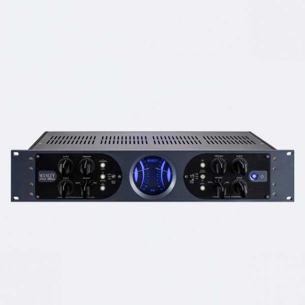
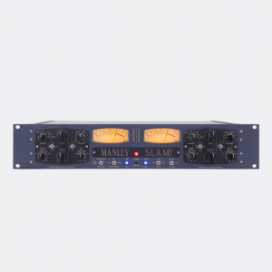
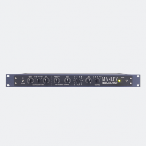
The Manley Nu Mu Stereo Limiter Compressor uses the special T-Bar mod tube front end of the legendary Variable Mu® with same super smooth side chain and timing characteristics followed by a high voltage discrete and FET solid-state amplifying and output stage for a faster and punchier audio path. It is like a “clean” version of the Variable Mu, especially suited for modern digital and electronic music where you don’t necessarily need to color or mask the sound like we did in the early days of digital.
Featuring Manley’s new HIP function, the Manley Nu Mu finesses dynamic control to bring up lower level details without knocking the life out of exciting transients. Smartly engineered to build efficiently and esthetically designed to elicit ravishing compliments from your clients, both visually and ergonomically, the Manley Nu Mu breaks new ground in performance and value, all proudly hand-built in California, of course!
Workflow:
1. OUTPUT CONTROL. The OUTPUT control is available on both the L and R channels. It adjusts the output level of that audio channel. Unity gain is about the ninth marking, or 11 o’clock.
2. THRESHOLD CONTROL. The THRESHOLD control is available on both the L and R channels. THRESHOLD or gain reduction sets the necessary amplitude for compression or limiting to take effect. The most extreme effect is when the control knob is set to MIN or fully counter-clockwise.
3. COMPRESS / LIMIT SWITCH. This switch allows the Nu Mu to use two different compression ratios, offering either Compression at approximately 3:1 when the switch is engaged and illuminated, or Limiting at approximately a 10:1 ratio.
4. IN / BYPASS SWITCH. The BYPASS switch in the Nu Mu is a ‘Hardwire’ bypass for maximum performance. If the switch is engaged and illuminated to the “IN” position the audio will pass through either the Limiter or Compressor, so all the front panel controls will function. Use this switch to verify that the limiting or compressing is not messing up the original sound but enhancing it or at least leveling the volume.
5. VU METER. The Large custom VU meters allow easy tracking of both channels with the Nu Mu. It shows the amount of gain reduction in dB from the 0 dB mark, when the switch (7) is set to REDUCTION. When this switch is selected to O/P and illuminated, the meter measures the output in decibels.
6. HIP CONTROL. The “Hip” control allows compression to happen at lower volumes (lower in the dynamic range spectrum) but leaves the louder dynamics alone while still compressing the overall signal. You get louder soft sections and original dynamics of the louder sections. Previously the only way to get around this issue has been parallel compression, where the compressed signal is mixed with the uncompressed signal. Our “Hip” control achieves a similar effect while being easier to use, requiring less hardware (no need for extra mixing externally).
7. METER SELECT SWITCH. The Meter select switch allows the user to monitor either Gain Reduction or the Output of the unit. When the switch is engaged and illuminated, the output of the particular channel you are monitoring is visible in the corresponding VU Meter.
8. ATTACK CONTROL. The ATTACK control determines how long the compressor takes to respond to signals above the threshold. The Attack control is continuously variable and determines the necessary length of a transient to initiate gain reduction.
With 63% gain reduction: SLOW 0.13s, MID 0.07s, FAST 0.013s.
With 90% gain reduction: SLOW 0.64s, MID 0.35s, FAST 0.064s.
Fully counter clockwise at the slowest setting will prevent most percussive signals from causing limiting or compression. It is available on both the left and the right channel.
9. RECOVERY CONTROL. The RECOVERY control determines how long the compressor takes to recover after the signal falls below the threshold level.
With 63% gain reduction recovery, five selections: 0.1s, 0.16, 0.32, 0.64s, 1.7s.
With 90% gain reduction recovery five selections: 0.227s, 0.368s, 0.736s, 1.6s, 3.87s.
10. LINK FUNCTION. When The LINK function is used it links the two Stereo channels together. The Left channel controls become the master linking THRESHOLD, ATTACK & the RECOVERY CONTROLS.
11. INPUT LEVEL SWITCH. The Input Level is controlled by a toggle switch. There is an Input Level control for each cannel. Three levels of attenuation are available. +3dB, 0dB and -3dB.
12. HP SC SWITCH. The High Pass Side Chain filter is factory set a 100Hz. When this switch is engaged and illuminated, everything above 100Hz will have the effect of limiting or compression. Useful if you want the bass to come through with full impact and limit or compress everything else.
13. POWER SWITCH. The Power Switch glows a soft blue color when an IEC power lead is connected to the unit. This indicates that the Nu Mu is in STANDBY mode. Engaging the power switch takes the Nu Mu out of standby mode and into warm-up mode. The power switch will illuminate to a brighter blue and the backlit VU meters will start to flash. This warm-up process last 30 seconds, after which the MUTE relays will lift and the VU meters will stop flashing.
